i guess this is where i tell you that you can make your own IR security camera cheaper then you can buy one, that might be true if you can create your own wireless camera, but not me. but if you do it this way it is a lot more fun and time consuming.
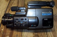
initially i just wanted to take a webcam and make it infrared, but in the process of disassembly i destroyed the lens. in my search for a replacement lens, the idea grew to use a camcorder so that i could use the zoom feature. i played around with the idea and this is what it turned out to be.
as you look over my project, i'm sure you say things like "Why did he do this.." and "He could have done that instead..." or even "What was he thinking??" well, i just used what i had and did it in the time frame set aside for it. i am always open for comments and suggestions. at the end i will list ideas that i would have like to have done or things i would have changed so that you could have the opportunity to make yours better.
the reason i call it a security camera is because it really cant be used for much else.
so here we go
materials:
- webcam
- camcorder - working or not, you'll just use the lens assembly
- infrared LEDs, or IR illuminator board kit
- computer power supply case, or any other type project box
- power supply, i used a 12v (from printer) and a 6v (from cell phone charger)
- misc switches
- wire, solder, rubberband
- nuts, bolts, scrap metal (for making/mounting brackets)
- hot glue, blank cds (the clear plastic ones)
- IR filter- make out of 35mm negatives, find the black part at the beginning of the strip
- patience
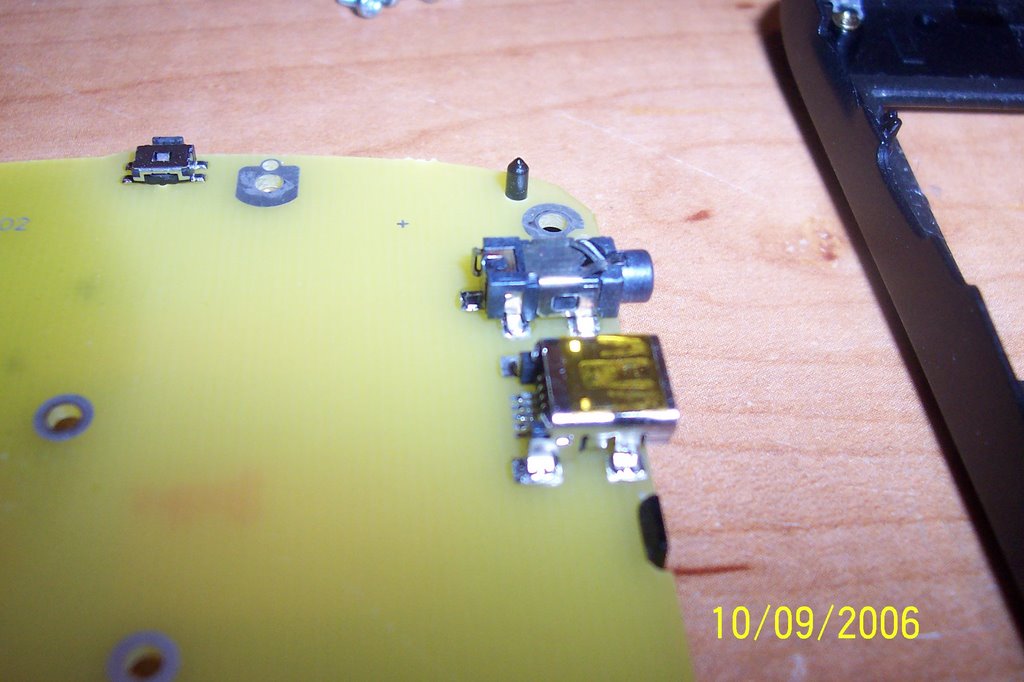
all the pictures can be found herenow we need to disassemble the webcam:
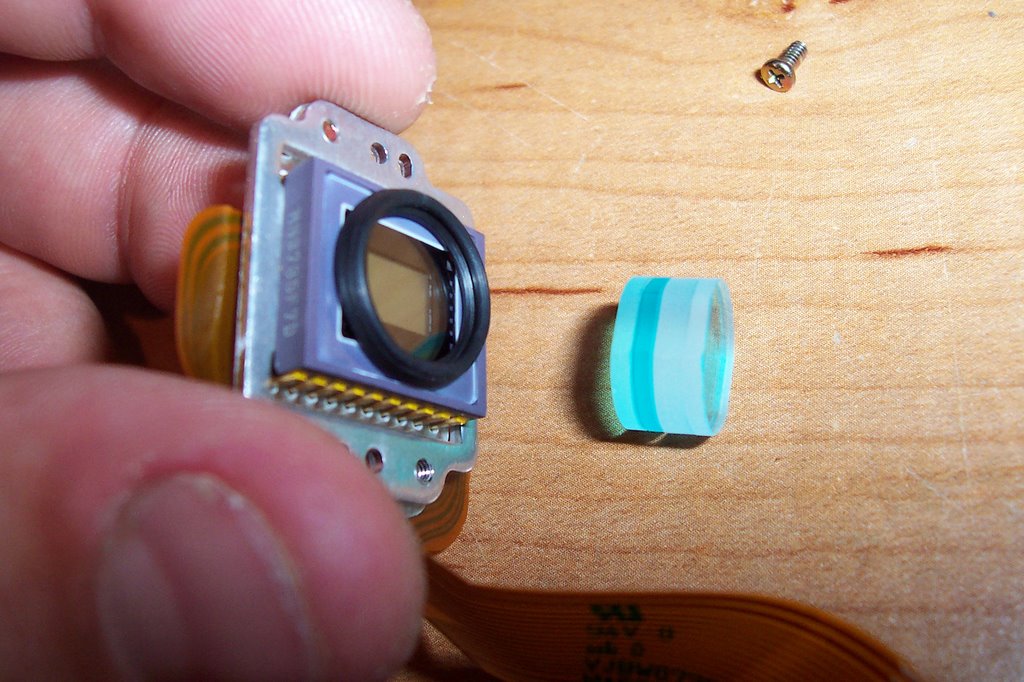
this is fairly straightforward, just find the screws and remove them. remove the lens assembly.

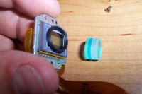
(if you want to use just the webcam then you need to disassemble the lens so you can take out the IR filter. sometimes it looks like a tiny red/blue square, but sometimes it is "painted" on the lens, if thats the case just scrape off. )
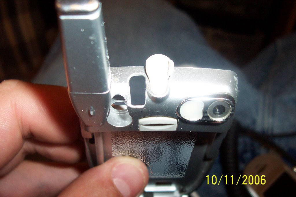
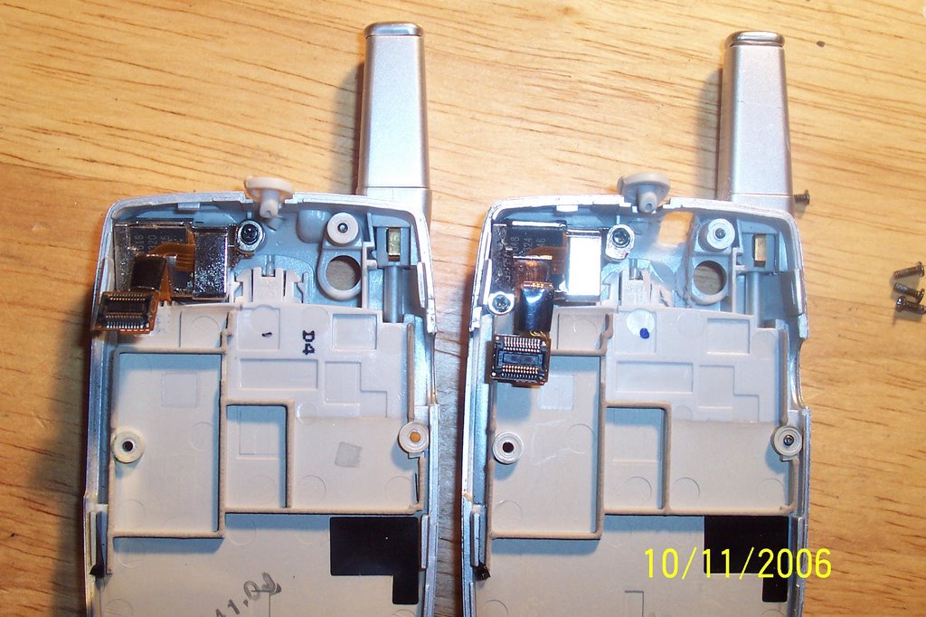
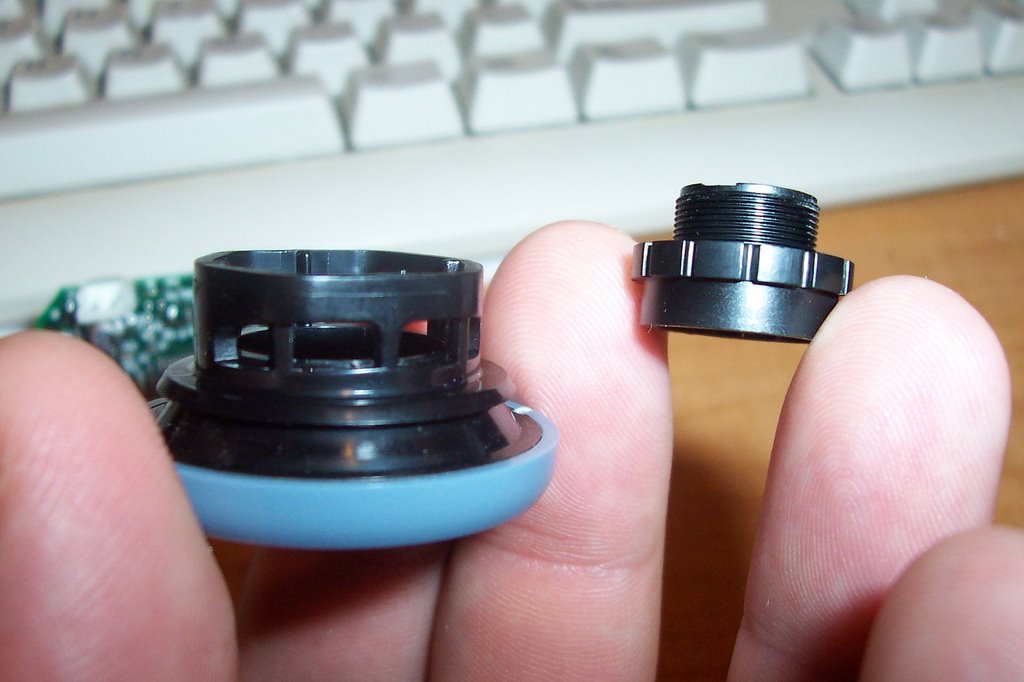
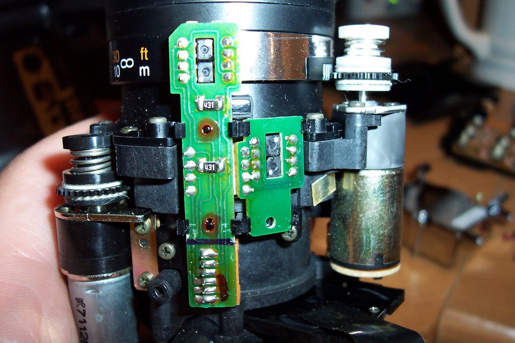
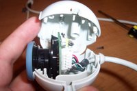
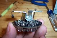
next you need to take apart the camcorder:
since camcorders vary by model use your own judgment on how to disassemble it. the most basic advice is to take your time. if the camcorder works, i suggest taking a lot of pictures so if in the end you decide to put it back together, it will be much simpler to do. just start removing screws and eventually itll come apart to the point that you need.
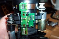
remember that all you need out of the camcorder is the lens assembly and the motors. a majority of camcorders have an auto focus feature, and if you are capable, save this feature for your project.
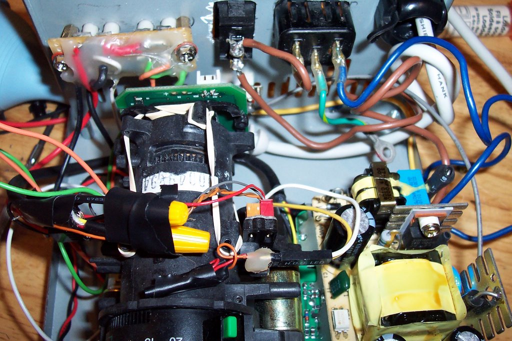
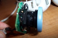
the blue lens is the IR filter that
blocks the IR light.
ok, now that the easy part is over you need to figure out how to put the pieces together.
assembly:
first thing to do is get the webcam connected to the lens assembly. this took a lot of trial/error tests on my part. the good news was the fact that my webcam fit excatly in the lens assembly, just like they were made for each other. you might have to create your own "couplings" to get yours to work. the bad news is that the optical sensor (the thing that catches the light on the webcam) will be a set distance from the lens assembly. since i didnt measure anything i had to adjust it by hand until it focused correctly. that took some time. as you can tell by the pictures, once i had the correct distance i just used a rubberband to mount it to the lens.
the IR filter is placed between the lens assembly and the webcam.
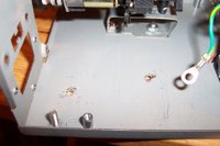
i did not plan where anything went to begin with. i just created as i went. i got a lot of metal filings everywhere as i cut the box, so use caution when cutting.
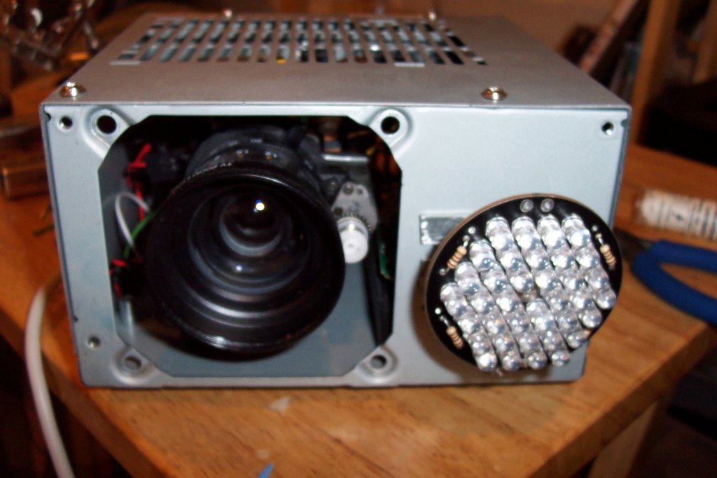
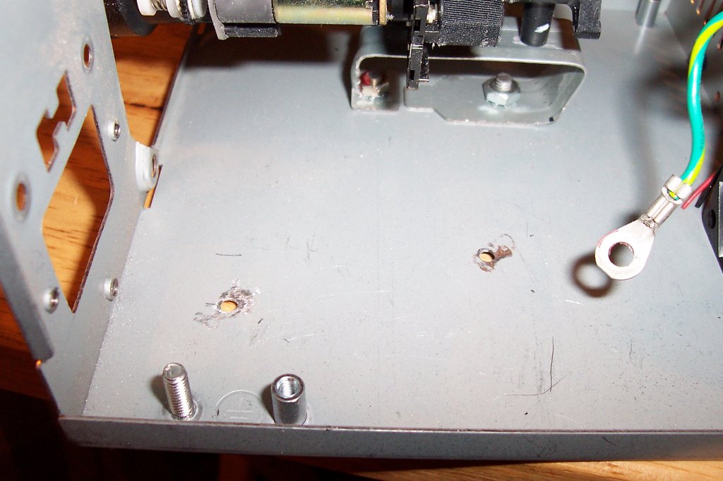
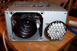
the first thing i mounted was the lens.
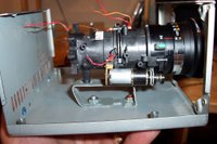
i placed it so that the lens would "see" through the opening where the power supply fan went. not perfect, but it was mounted.
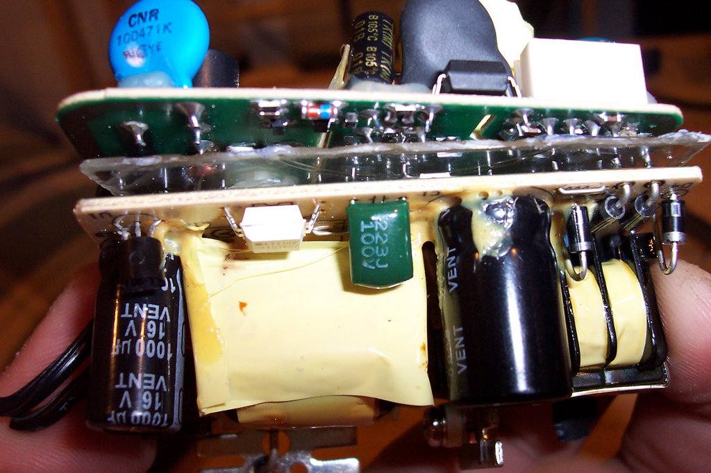
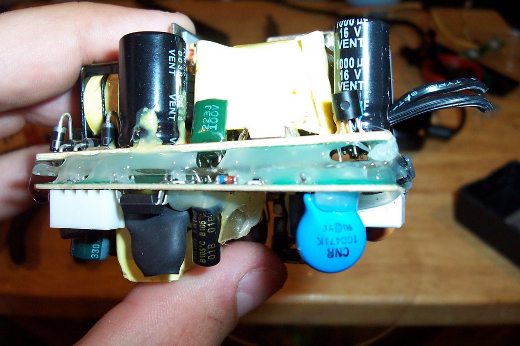
next i rigged my power supplies. -you can use whatever power you want- i used a 12volt from a printer to power the IR board, and a 6volt from cell phone charger to power the zoom/focus motors and the shutter.
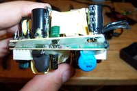
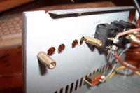
open up the power supplys. the quickest way i found was to use my dremel and the disk cutting attachment. take care not to cut too deep, you might cut something you dont want to. after i managed to get the boards free from their shells, i wired them together.
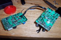
i got a plastic cd and cut a square out of it so i could use it for a "insulator" between the two power supplies.
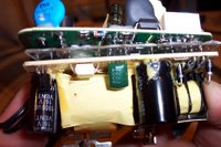
after everything was lined up, it all got "glued" together with hot glue (also a good insulator).
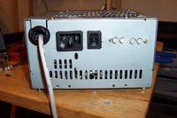
next mount the "shell"
of the power supply
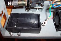
in the box to hold your new combo power in place.
next i build my IR illuminator board.
which i bought online:
bgmicro.com (LED 1007) it took me about 30 min to finish.
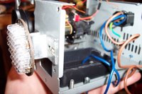
i then created a bracket so i could mount the IR to my case.
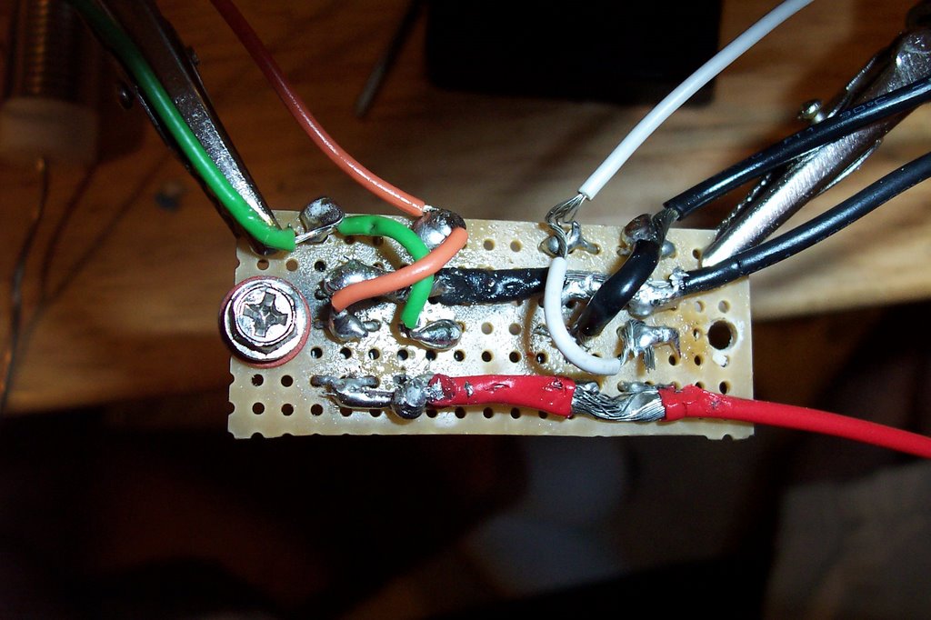
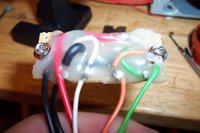
i used the camcorder switches
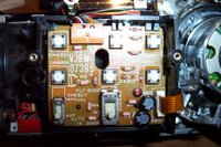
and some other of the same type switch from an old programmable coffee maker to control the zoom/focus motors.
i essentially created two 2 pole 2 throw switches
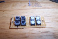
. it would have been better just to buy them, but its diy. initially i was going to create my own "breadboard" out of a cd, but then i found a real one to use. as you can see the construction of the switches is pretty simple
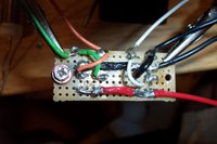
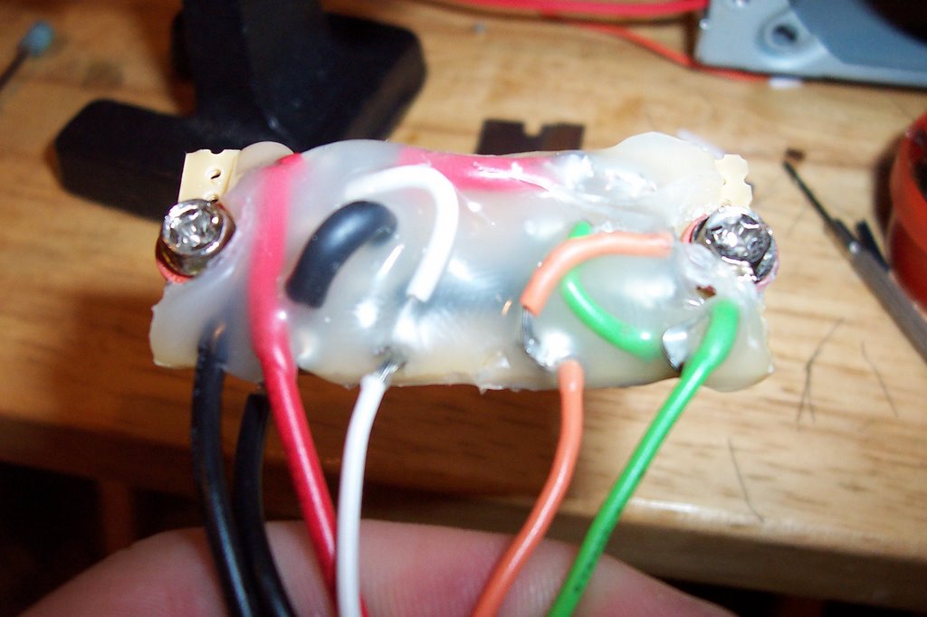
, after wiring just glob more hot glue on it.
(note: there is no short-circuit protection on this circuit, so use caution)
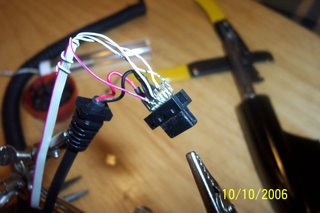
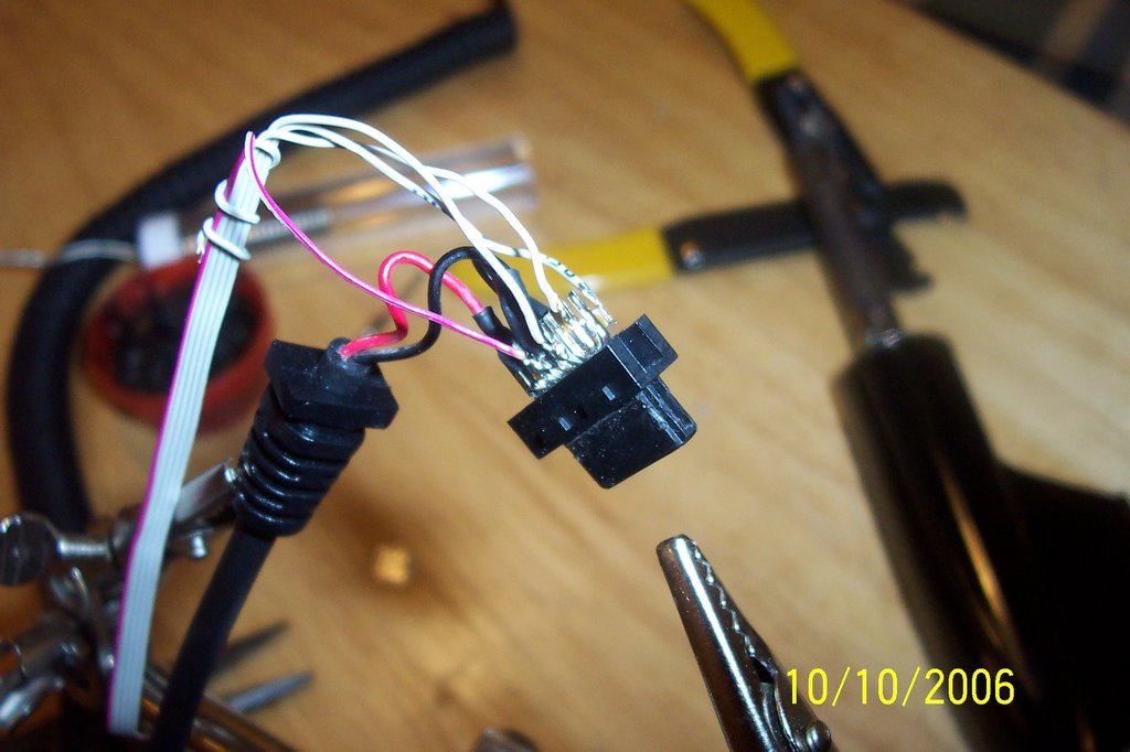
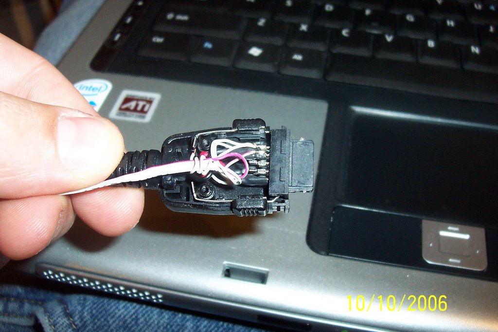
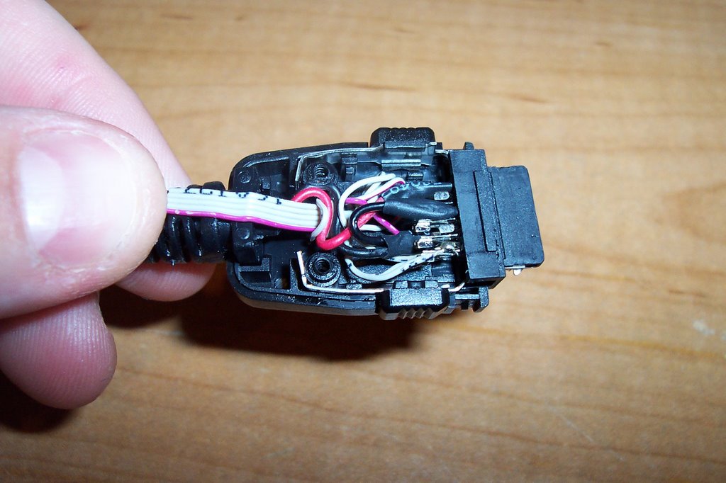
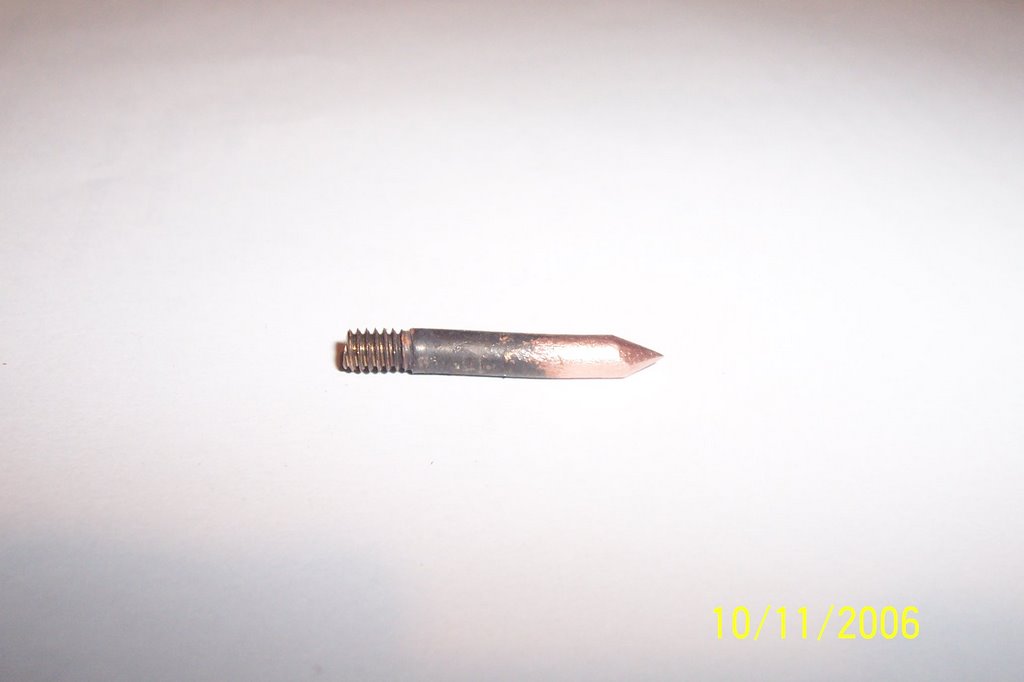
the wires connected to the motors were too small for me to use, so i "fixed" the connector. i pulled some right angle jumper pins off a computer cd player
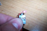
(the master/slave/CS pins) and connected those to the existing connector, then, with the very versatile hot glue, put them together. now i could use the computer type connectors to get them to work, (you know, HDD light/Reset sw/speaker etc...)
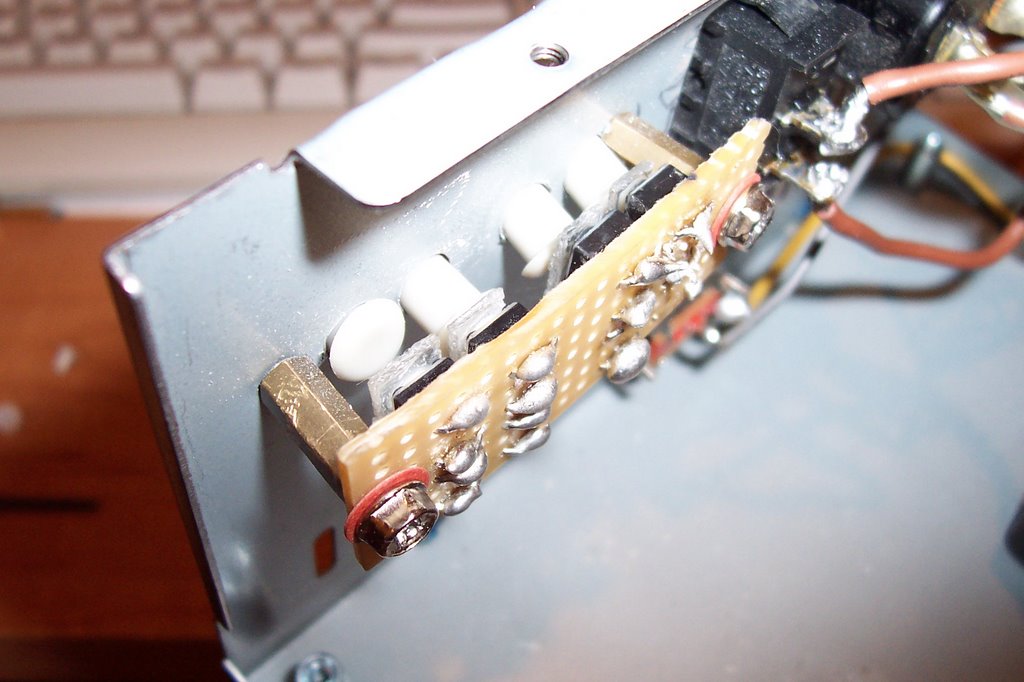
mount the switches

and power connectors to the box and wire everything up.

i put a master power switch, a 12v on/off power switch for IR light, and focus near/far and zoom in/out switches. the shutter opens automatically when the power is on.
if everything went well you will have a nice zoomable IR security camera!!
Now the list of "would-of/should-of/could-of":
- mount lens for pan/tilt capabilities
- power supply options: car adaptor, batteries, powered by usb (for portability)
- everything controlled via usb/software -zoom/pan/tilt/focus/shutter/ir filter, etc
- make it wireless - covert a router or something to control it over internet
- make it comparable to the D-LINK 6620G
a lot of possibilities. maybe ive pointed you in the right direction
more pictures are located
hereas always, have fun
here are some pictures for your viewing pleasure
note: i already know they are not quality pictures, making comments on the subject would be redundantly redundant :)
--the quality of the picture depends on the quality of the webcam you use.
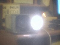
--first picture is taken using another ir camera (camera lets ALL light in, thats why its in color)

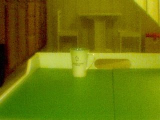
--next, base picture of coffee mug taken with same camera (5ft distance)
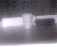
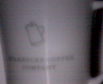
--third picture taken with project camera same distance away
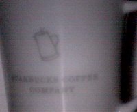
--forth picture at max zoom (6x)
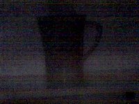
--last picture is taken max zoom at 20ft distance
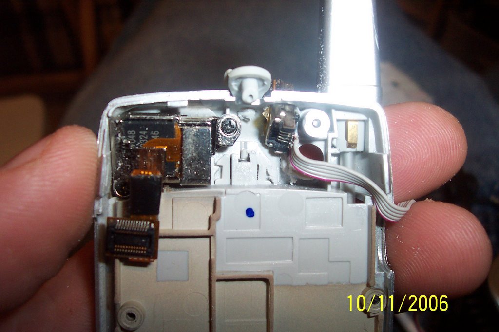
bonus picture:
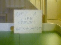


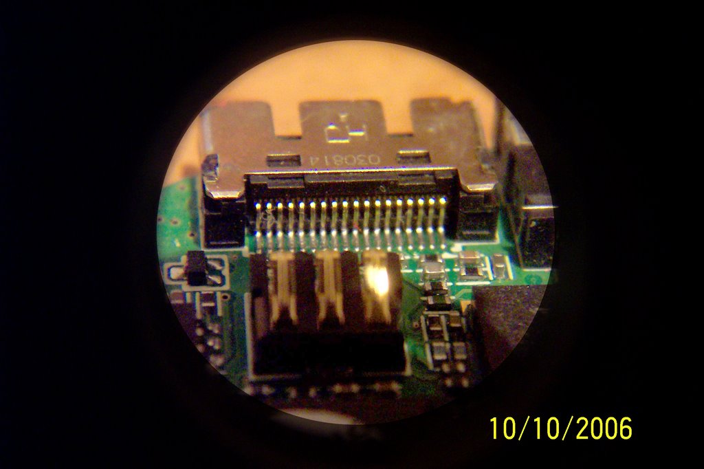
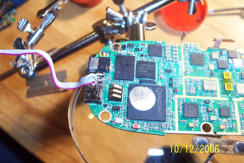
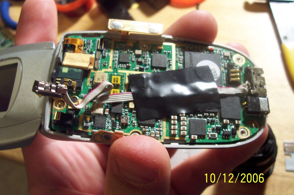
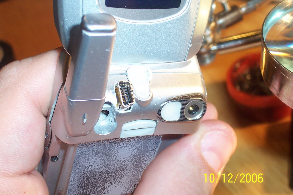
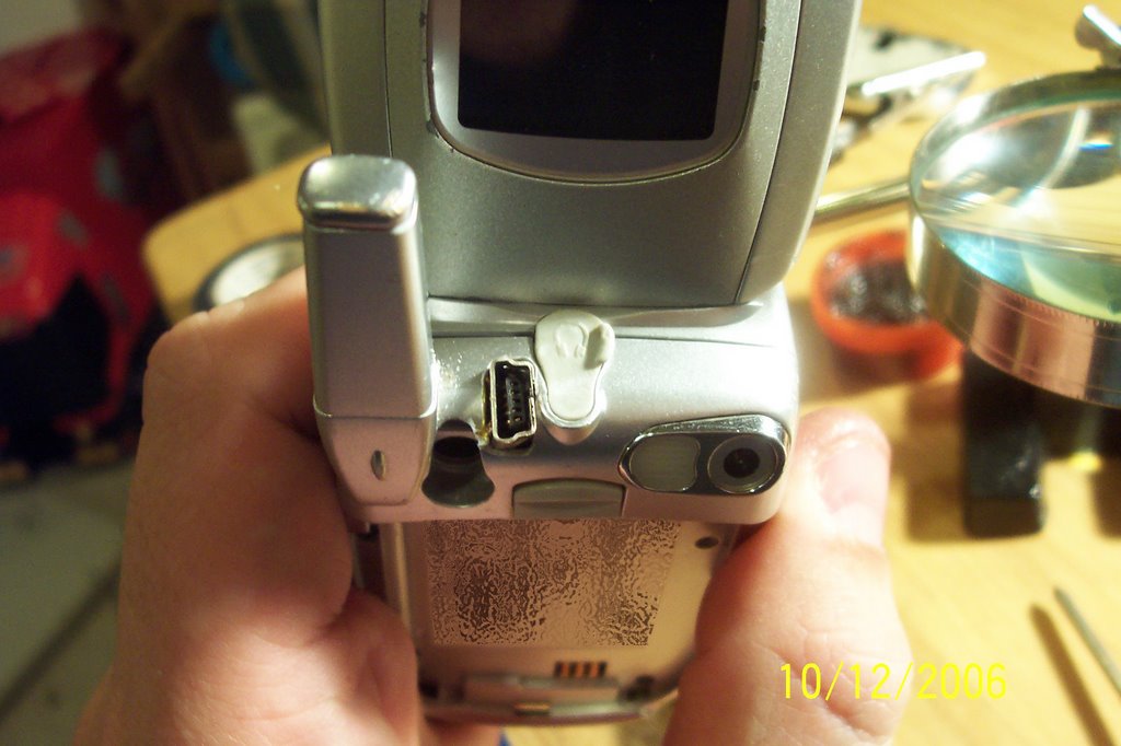
 So you dont want to cut up your phone....( if you do... )