

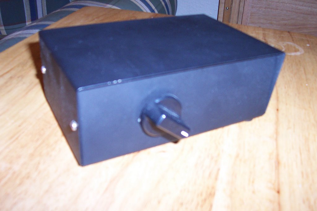
 Procrastination has its price. As I finally decided to put up my projects online, I notice that there are others like myself, who like to save some money, and have their projects up and running. So, if I come across others that are the same as mine (or at least the same idea) I will post to their pages also.
The DIY RCA Switch Box is not a new idea, (LifeHacker), just a little difficult to do. What you need to accomplish such a task is patients and time. You can always go and buy one, but if you need a certain configuration that might be expensive.
For mine, I needed 4 inputs to 1 output, and I didn't feel like spending more then $10.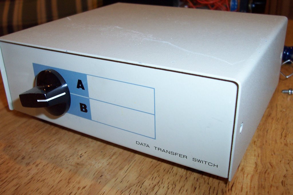 I found an old parallel printer A/B switch box, which was not being used (USB printers now), so I took it apart.
The first thing was that it was an A/B switch box and I needed an A/B/C/D switch box, well I got lucky. The key is in the switch itself. (more on that in a bit)
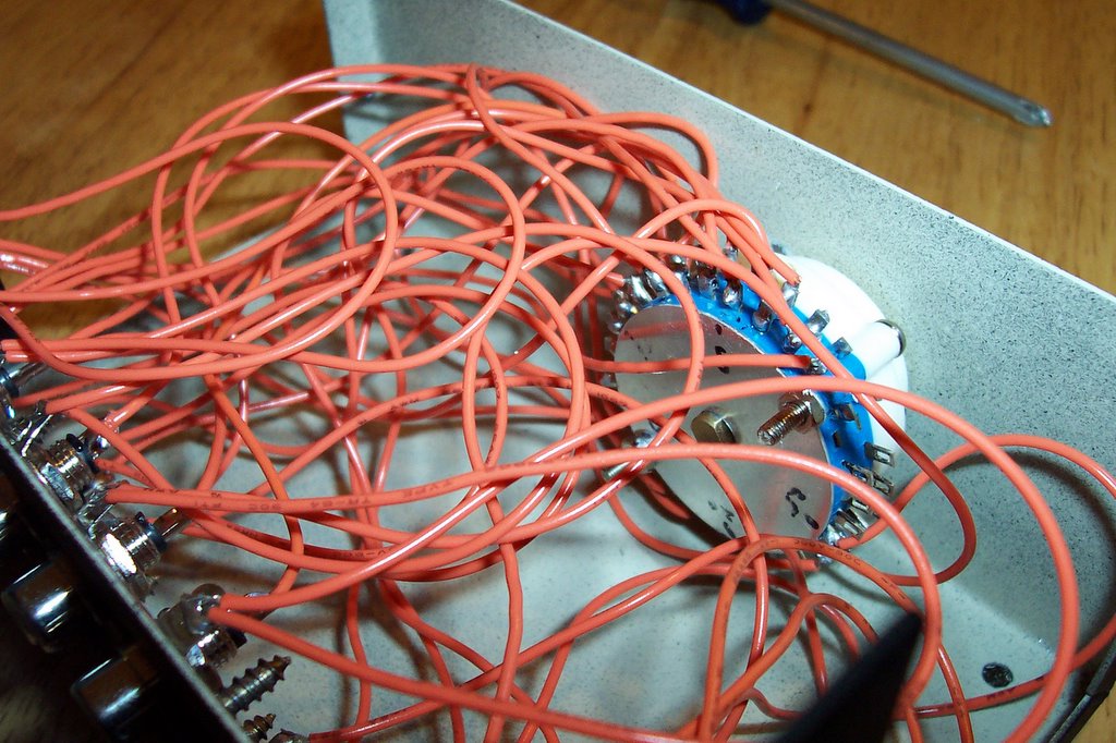
When you take it apart it might seem just a little overwhelming with all the wires, but in fact, it is really simple.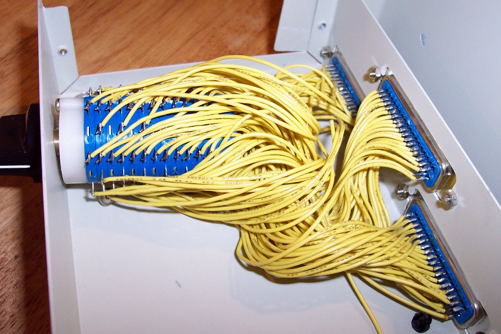 You can either unsolder all the wires off or just cut them at the end NOT connected to switch.
I would recommend unsoldering off the switch end for easier testing of switch.
Now for the fun part: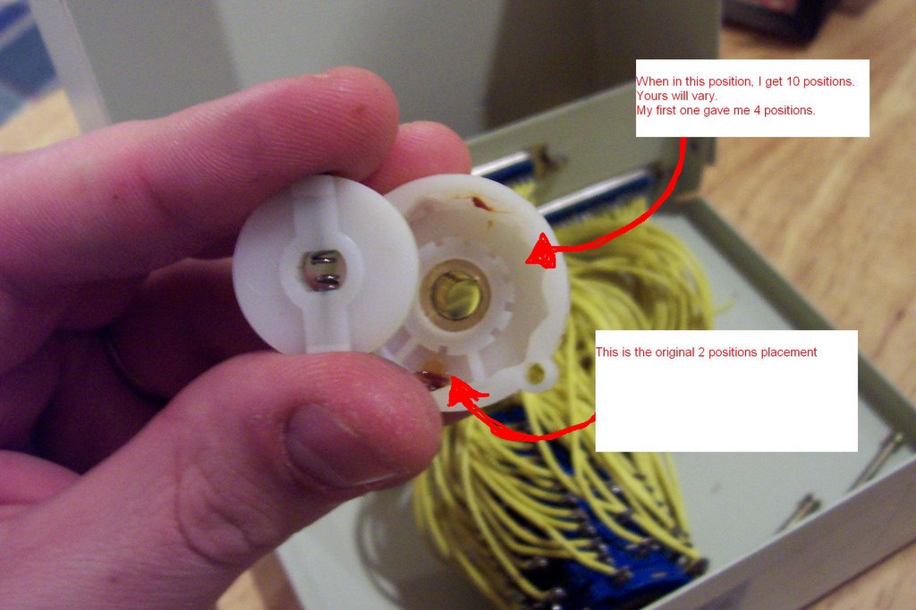
Carefully take the switch apart. Now this part is hard to explain, the switches I had were A/B switches, but inside I flipped over the "how-many-positions" plastic piece and got what I wanted.
Now after we get the switch to the number of positions we need, its time for the task of figuring out how to set it up.
Because each application and switch are going to be different then mine, I will show how I did mine, and you can use that as a guide for yours.
All you have to do is get your trusty multi-tester with an ohm or continuity checker on it and start figuring your wiring diagram.
Here's a scan of mine.
 The color codes are for the switch positions. on the 4th position, I was only able to get mono because I broke one of the mini-contact points inside the switch.
I don't know if you will be able to make heads or tails over my schematics, but maybe they'll help someone.
After you get the switch figured out, all you do is mount the connectors and solder the wires to them.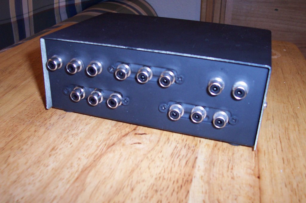 I used the old A/B switch box as the new one, but I had to cover those huge holes where the parallel ports were. I used expansion card place holders. You know, those metal brackets you put in to cover the hole that's left from removing that unused modem out of your computer.
That worked out well. Now my box is finished, except for the labeling on the front. I can connect my DVD, PS1, Camcorder, and for the mono jack, I got my computer plugged into that one. (s-video to composite cable).
I hope you can find this a help. Because you are in control of the wiring, you can make your own S-Video switch box, or DVI switch box, etc.
Just have fun
-=** UPDATE **=-
I have realized that my diagram is not easily interpreted, so I'll try to explain it.
First take a look at the picture of the actual switch. You will notice a lot of metal tabs sticking out. Those are the contact point to solder to. Now look at the diagram. You will notice that it is color coded. Those colors represent which contacts have continuity when in the corresponding switch position. There are three contacts per position. One for input and Two for output (A/B).
--For Example: Pins 4,5,6 have Blue and Green. ---Pin 4 connects with Pin 5 in switch position 1 --- Pin 6 connects with Pin 5 in switch position 2-- So you can have video-in on Pin 5 and video-out on pin 4 and 6.
The Yellow position didn't have any continuity to other pins, so I had to use another "disk". The switch I took apart was made up of several "disks". Yours might be different, so you'll just have to get out that trusty multi-meter to test the continuity of your disks.
If you have ANY questions, or I did not explain well enough, just send me and email at computerguru365 (at) gmail (dot) com. I will update as needed.
Tuesday, February 14, 2006
DIY RCA Switch Box **UPDATED**


Subscribe to:
Posts (Atom)


